Wireless
Communication Tutorial
Wireless communication
involves the transmission of information over a distance without the help of
wires, cables or any other forms of electrical conductors.
Wireless communication
is a broad term that incorporates all procedures and forms of connecting and
communicating between two or more devices using a wireless signal through
wireless communication technologies and devices.
Features of Wireless
Communication
The evolution of
wireless technology has brought many advancements with its effective features.
·
The transmitted distance can be anywhere between a few meters (for
example, a television's remote control) and thousands of kilometers (for
example, radio communication).
·
Wireless communication can be used for cellular telephony,
wireless access to the internet, wireless home networking, and so on.
·
Other examples of applications of radio wireless technology
include GPS units, garage door openers, wireless computer mice, keyboards and
headsets, headphones, radio receivers, satellite television, broadcast
television and cordless telephones.

Wireless - Advantages
Wireless communication
involves transfer of information without any physical connection between two or
more points. Because of this absence of any 'physical infrastructure', wireless
communication has certain advantages. This would often include collapsing
distance or space.
Wireless communication
has several advantages; the most important ones are discussed below −
Cost effectiveness
Wired communication
entails the use of connection wires. In wireless networks, communication does
not require elaborate physical infrastructure or maintenance practices. Hence
the cost is reduced.
Example − Any company
providing wireless communication services does not incur a lot of costs, and as
a result, it is able to charge cheaply with regard to its customer fees.
Flexibility
Wireless communication
enables people to communicate regardless of their location. It is not necessary
to be in an office or some telephone booth in order to pass and receive
messages.
Miners in the outback
can rely on satellite phones to call their loved ones, and thus, help improve
their general welfare by keeping them in touch with the people who mean the
most to them.
Convenience
Wireless communication
devices like mobile phones are quite simple and therefore allow anyone to use
them, wherever they may be. There is no need to physically connect anything in
order to receive or pass messages.
Example − Wireless
communications services can also be seen in Internet technologies such as
Wi-Fi. With no network cables hampering movement, we can now connect with
almost anyone, anywhere, anytime.
Speed
Improvements can also be
seen in speed. The network connectivity or the accessibility were much improved
in accuracy and speed.
Example − A wireless
remote can operate a system faster than a wired one. The wireless control of a
machine can easily stop its working if something goes wrong, whereas direct
operation can’t act so fast.
Accessibility
The wireless technology helps
easy accessibility as the remote areas where ground lines can’t be properly
laid, are being easily connected to the network.
Example − In rural
regions, online education is now possible. Educators no longer need to travel
to far-flung areas to teach their lessons. Thanks to live streaming of their
educational modules.
Constant connectivity
Constant connectivity
also ensures that people can respond to emergencies relatively quickly.
Example − A wireless
mobile can ensure you a constant connectivity though you move from place to
place or while you travel, whereas a wired land line can’t.
DCN - Wireless Transmission
Wireless transmission is
a form of unguided media. Wireless communication involves no physical link
established between two or more devices, communicating wirelessly. Wireless
signals are spread over in the air and are received and interpreted by
appropriate antennas.
When an antenna is
attached to electrical circuit of a computer or wireless device, it converts
the digital data into wireless signals and spread all over within its frequency
range. The receptor on the other end receives these signals and converts them
back to digital data.
A little part of
electromagnetic spectrum can be used for wireless transmission.

Radio Transmission
Radio frequency is
easier to generate and because of its large wavelength it can penetrate through
walls and structures alike.Radio waves can have wavelength from 1 mm – 100,000
km and have frequency ranging from 3 Hz (Extremely Low Frequency) to 300 GHz (Extremely
High Frequency). Radio frequencies are sub-divided into six bands.
Radio waves at lower
frequencies can travel through walls whereas higher RF can travel in straight
line and bounce back.The power of low frequency waves decreases sharply as they
cover long distance. High frequency radio waves have more power.
Lower frequencies such
as VLF, LF, MF bands can travel on the ground up to 1000 kilometers, over the
earth’s surface.

Radio waves of high
frequencies are prone to be absorbed by rain and other obstacles. They use
Ionosphere of earth atmosphere. High frequency radio waves such as HF and VHF
bands are spread upwards. When they reach Ionosphere, they are refracted back
to the earth.

Microwave Transmission
Electromagnetic waves
above 100 MHz tend to travel in a straight line and signals over them can be
sent by beaming those waves towards one particular station. Because Microwaves
travels in straight lines, both sender and receiver must be aligned to be
strictly in line-of-sight.
Microwaves can have
wavelength ranging from 1 mm – 1 meter and frequency ranging from 300 MHz to
300 GHz.

Microwave antennas
concentrate the waves making a beam of it. As shown in picture above, multiple
antennas can be aligned to reach farther. Microwaves have higher frequencies
and do not penetrate wall like obstacles.
Microwave transmission
depends highly upon the weather conditions and the frequency it is using.
Infrared Transmission
Infrared wave lies in
between visible light spectrum and microwaves. It has wavelength of 700-nm to
1-mm and frequency ranges from 300-GHz to 430-THz.
Infrared wave is used
for very short range communication purposes such as television and it’s remote.
Infrared travels in a straight line hence it is directional by nature. Because of
high frequency range, Infrared cannot cross wall-like obstacles.
Light Transmission
Highest most
electromagnetic spectrum which can be used for data transmission is light or
optical signaling. This is achieved by means of LASER.
Because of frequency light
uses, it tends to travel strictly in straight line.Hence the sender and
receiver must be in the line-of-sight. Because laser transmission is
unidirectional, at both ends of communication the laser and the photo-detector
needs to be installed. Laser beam is generally 1mm wide hence it is a work of
precision to align two far receptors each pointing to lasers source.

Laser works as Tx
(transmitter) and photo-detectors works as Rx (receiver).
Lasers cannot penetrate
obstacles such as walls, rain, and thick fog. Additionally, laser beam is
distorted by wind, atmosphere temperature, or variation in temperature in the
path.
Laser is safe for data
transmission as it is very difficult to tap 1mm wide laser without interrupting
the communication channel.
DCN - Multiplexing
Multiplexing is a
technique by which different analog and digital streams of transmission can be
simultaneously processed over a shared link. Multiplexing divides the high
capacity medium into low capacity logical medium which is then shared by
different streams.
Communication is
possible over the air (radio frequency), using a physical media (cable), and
light (optical fiber). All mediums are capable of multiplexing.
When multiple senders
try to send over a single medium, a device called Multiplexer divides the
physical channel and allocates one to each. On the other end of communication,
a De-multiplexer receives data from a single medium, identifies each, and sends
to different receivers.
Frequency Division
Multiplexing
When the carrier is frequency,
FDM is used. FDM is an analog technology. FDM divides the spectrum or carrier
bandwidth in logical channels and allocates one user to each channel. Each user
can use the channel frequency independently and has exclusive access of it. All
channels are divided in such a way that they do not overlap with each other.
Channels are separated by guard bands. Guard band is a frequency which is not
used by either channel.

Time Division
Multiplexing
TDM is applied primarily
on digital signals but can be applied on analog signals as well. In TDM the
shared channel is divided among its user by means of time slot. Each user can
transmit data within the provided time slot only. Digital signals are divided
in frames, equivalent to time slot i.e. frame of an optimal size which can be
transmitted in given time slot.
TDM works in
synchronized mode. Both ends, i.e. Multiplexer and De-multiplexer are timely
synchronized and both switch to next channel simultaneously.

When channel A transmits
its frame at one end,the De-multiplexer provides media to channel A on the
other end.As soon as the channel A’s time slot expires, this side switches to
channel B. On the other end, the De-multiplexer works in a synchronized manner
and provides media to channel B. Signals from different channels travel the
path in interleaved manner.
Wavelength Division
Multiplexing
Light has different
wavelength (colors). In fiber optic mode, multiple optical carrier signals are
multiplexed into an optical fiber by using different wavelengths. This is an
analog multiplexing technique and is done conceptually in the same manner as
FDM but uses light as signals.

Further, on each
wavelength time division multiplexing can be incorporated to accommodate more
data signals.
Code Division
Multiplexing
Multiple data signals
can be transmitted over a single frequency by using Code Division Multiplexing.
FDM divides the frequency in smaller channels but CDM allows its users to full
bandwidth and transmit signals all the time using a unique code. CDM uses orthogonal
codes to spread signals.
Each station is assigned
with a unique code, called chip. Signals travel with these codes independently,
inside the whole bandwidth.The receiver knows in advance the chip code signal
it has to receive.
Spread Spectrum Modulation
A collective class of
signaling techniques are employed before transmitting a signal to provide a
secure communication, known as the Spread Spectrum Modulation. The
main advantage of spread spectrum communication technique is to prevent
“interference” whether it is intentional or unintentional.
The signals modulated
with these techniques are hard to interfere and cannot be jammed. An intruder
with no official access is never allowed to crack them. Hence, these techniques
are used for military purposes. These spread spectrum signals transmit at low
power density and has a wide spread of signals.
Pseudo-Noise Sequence
A coded sequence
of 1s and 0s with certain auto-correlation
properties, called as Pseudo-Noise coding sequence is used in
spread spectrum techniques. It is a maximum-length sequence, which is a type of
cyclic code.
Narrow-band and
Spread-spectrum Signals
Both the Narrow band and
Spread spectrum signals can be understood easily by observing their frequency
spectrum as shown in the following figures.
Narrow-band Signals
The Narrow-band signals
have the signal strength concentrated as shown in the following frequency
spectrum figure.

Following are some of
its features −
- Band of signals
occupy a narrow range of frequencies.
- Power density
is high.
- Spread of
energy is low and concentrated.
Though the features are
good, these signals are prone to interference.
Spread Spectrum Signals
The spread spectrum
signals have the signal strength distributed as shown in the following
frequency spectrum figure.

Following are some of
its features −
- Band of signals
occupy a wide range of frequencies.
- Power density
is very low.
- Energy is wide
spread.
With these features, the
spread spectrum signals are highly resistant to interference or jamming. Since
multiple users can share the same spread spectrum bandwidth without interfering
with one another, these can be called as multiple access techniques.
FHSS and DSSS / CDMA
Spread spectrum multiple
access techniques uses signals which have a transmission bandwidth of a
magnitude greater than the minimum required RF bandwidth.
These are of two types.
- Frequency
Hopped Spread Spectrum (FHSS)
- Direct Sequence
Spread Spectrum (DSSS)
Frequency Hopped Spread Spectrum (FHSS)
This is frequency
hopping technique, where the users are made to change the frequencies of usage,
from one to another in a specified time interval, hence called as frequency
hopping. For example, a frequency was allotted to sender 1 for a particular
period of time. Now, after a while, sender 1 hops to the other frequency and
sender 2 uses the first frequency, which was previously used by sender 1. This
is called as frequency reuse.
The frequencies of the
data are hopped from one to another in order to provide a secure transmission.
The amount of time spent on each frequency hop is called as Dwell time.
Direct Sequence Spread Spectrum (DSSS)
Whenever a user wants to
send data using this DSSS technique, each and every bit of the user data is
multiplied by a secret code, called as chipping code. This chipping
code is nothing but the spreading code which is multiplied with the original
message and transmitted. The receiver uses the same code to retrieve the
original message.
Comparison between FHSS
and DSSS/CDMA
Both the spread spectrum
techniques are popular for their characteristics. To have a clear understanding,
let us take a look at their comparisons.
|
FHSS
|
DSSS / CDMA
|
|
Multiple
frequencies are used
|
Single
frequency is used
|
|
Hard to
find the user’s frequency at any instant of time
|
User
frequency, once allotted is always the same
|
|
Frequency
reuse is allowed
|
Frequency
reuse is not allowed
|
|
Sender
need not wait
|
Sender has
to wait if the spectrum is busy
|
|
Power
strength of the signal is high
|
Power
strength of the signal is low
|
|
Stronger
and penetrates through the obstacles
|
It is
weaker compared to FHSS
|
|
It is
never affected by interference
|
It can be
affected by interference
|
|
It is
cheaper
|
It is
expensive
|
|
This is
the commonly used technique
|
This
technique is not frequently used
|
Advantages of Spread
Spectrum
Following are the
advantages of spread spectrum −
- Cross-talk
elimination
- Better output
with data integrity
- Reduced effect
of multipath fading
- Better security
- Reduction in
noise
- Co-existence
with other systems
- Longer
operative distances
- Hard to detect
- Not easy to
demodulate/decode
- Difficult to
jam the signals
Although spread spectrum
techniques were originally designed for military uses, they are now being used
widely for commercial purpose.
Antenna Theory - Fundamentals
A person, who needs to
convey a thought, an idea or a doubt, can do so by voice communication.
The following
illustration shows two individuals communicating with each other. Here,
communication takes place through sound waves. However, if two
people want to communicate who are at longer distances, then we have to convert
these sound waves into electromagnetic waves. The device, which
converts the required information signal into electromagnetic waves, is known
as an Antenna.

What is an Antenna ?
An Antenna is a
transducer, which converts electrical power into electromagnetic waves and vice
versa.
An Antenna can be used
either as a transmitting antenna or a receiving
antenna.
·
A transmitting antenna is one, which converts
electrical signals into electromagnetic waves and radiates them.
·
A receiving antenna is one, which converts electromagnetic
waves from the received beam into electrical signals.
·
In two-way communication, the same antenna can be used for both
transmission and reception.
Antenna can also be
termed as an Aerial. Plural of it is, antennae or antennas.
Now-adays, antennas have undergone many changes, in accordance with their size
and shape. There are many types of antennas depending upon their wide variety
of applications.
Following pictures are
examples of different types of Antennas.

In this chapter, you are
going to learn the basic concepts of antenna, specifications and different
types of antennas.
Need of Antenna
In the field of
communication systems, whenever the need for wireless communication arises,
there occurs the necessity of an antenna. Antenna has the capability
of sending or receiving the electromagnetic waves for the sake of
communication, where you cannot expect to lay down a wiring system. The
following scenario explains this.
Scenario
In order to contact a
remote area, the wiring has to be laid down throughout the whole route along
the valleys, the mountains, the tedious paths, the tunnels etc., to reach the
remote location. The evolution of wireless technology has made this whole
process very simple. Antenna is the key element of this wireless technology.

In the above image, the
antennas help the communication to be established in the whole area, including
the valleys and mountains. This process would obviously be easier than laying a
wiring system throughout the area.
Radiation Mechanism
The sole functionality
of an antenna is power radiation or reception. Antenna
(whether it transmits or receives or does both) can be connected to the
circuitry at the station through a transmission line. The functioning of an
antenna depends upon the radiation mechanism of a transmission line.
A conductor, which is
designed to carry current over large distances with minimum losses, is termed
as a transmission line. For example, a wire, which is connected to
an antenna. A transmission line conducting current with uniform velocity, and
the line being a straight one with infinite extent, radiates no power.
For a transmission line,
to become a waveguide or to radiate power, has to be processed as such.
·
If the power has to be radiated, though the current conduction is with
uniform velocity, the wire or transmission line should be bent, truncated or
terminated.
·
If this transmission line has current, which accelerates or
decelerates with a timevarying constant, then it radiates the power even though
the wire is straight.
·
The device or tube, if bent or terminated to radiate energy, then
it is called as waveguide. These are especially used for the
microwave transmission or reception.
This can be well
understood by observing the following diagram −

The above diagram
represents a waveguide, which acts as an antenna. The power from the
transmission line travels through the waveguide which has an aperture, to
radiate the energy.
Basic Types of Antennas
Antennas may be divided
into various types depending upon −
·
The physical structure of the antenna.
·
The frequency ranges of operation.
·
The mode of applications etc.
Physical structure
Following are the types
of antennas according to the physical structure. You will learn about these
antennas in later chapters.
- Wire antennas
- Aperture
antennas
- Reflector
antennas
- Lens antennas
- Micro strip
antennas
- Array antennas
Frequency of operation
Following are the types
of antennas according to the frequency of operation.
- Very Low
Frequency (VLF)
- Low Frequency
(LF)
- Medium
Frequency (MF)
- High Frequency
(HF)
- Very High
Frequency (VHF)
- Ultra High
Frequency (UHF)
- Super High
Frequency (SHF)
- Micro wave
- Radio wave
Mode of Applications
Following are the types
of antennas according to the modes of applications −
- Point-to-point
communications
- Broadcasting
applications
- Radar
communications
- Satellite
communications
Medium Access
Control Sublayer (MAC sublayer)
The medium access control (MAC) is a sublayer
of the data link layer of the open system interconnections (OSI) reference
model for data transmission. It is responsible for flow control and
multiplexing for transmission medium. It controls the transmission of data
packets via remotely shared channels. It sends data over the network interface
card.
MAC Layer in the OSI Model
The Open System Interconnections (OSI) model
is a layered networking framework that conceptualizes how communications should
be done between heterogeneous systems. The data link layer is the second lowest
layer. It is divided into two sublayers −
·
The logical link control (LLC) sublayer
·
The medium access control (MAC) sublayer
The following diagram depicts the position of
the MAC layer −

Functions of MAC Layer
·
It provides an abstraction of the physical layer to the LLC and
upper layers of the OSI network.
·
It is responsible for encapsulating frames so that they are
suitable for transmission via the physical medium.
·
It resolves the addressing of source station as well as the
destination station, or groups of destination stations.
·
It performs multiple access resolutions when more than one data
frame is to be transmitted. It determines the channel access methods for
transmission.
·
It also performs collision resolution and initiating
retransmission in case of collisions.
·
It generates the frame check sequences and thus contributes to
protection against transmission errors.
MAC Addresses
MAC address or media access control address
is a unique identifier allotted to a network interface controller (NIC) of a
device. It is used as a network address for data transmission within a network
segment like Ethernet, Wi-Fi, and Bluetooth.
MAC address is assigned to a network adapter
at the time of manufacturing. It is hardwired or hard-coded in the network
interface card (NIC). A MAC address comprises of six groups of two hexadecimal digits,
separated by hyphens, colons, or no separators. An example of a MAC address is
00:0A:89:5B:F0:11.
Wireless Communication - Multiple Access
Multiple access schemes
are used to allow many mobile users to share simultaneously a finite amount of
radio spectrum.
Multiple Access
Techniques
In wireless
communication systems, it is often desirable to allow the subscriber to send
information simultaneously from the mobile station to the base station while
receiving information from the base station to the mobile station.
A cellular system
divides any given area into cells where a mobile unit in each cell communicates
with a base station. The main aim in the cellular system design is to be able
to increase the capacity of the channel, i.e., to handle as many calls
as possible in a given bandwidth with a sufficient level of quality of service.
There are several
different ways to allow access to the channel. These includes mainly the
following −
- Frequency
division multiple-access (FDMA)
- Time division multiple-access
(TDMA)
- Code division
multiple-access (CDMA)
- Space division
multiple access (SDMA)
Depending on how the
available bandwidth is allocated to the users, these techniques can be
classified as narrowband and wideband systems.
Narrowband Systems
Systems operating with
channels substantially narrower than the coherence bandwidth are called as
Narrow band systems. Narrow band TDMA allows users to use the same channel but
allocates a unique time slot to each user on the channel, thus separating a small
number of users in time on a single channel.
Wideband Systems
In wideband systems, the
transmission bandwidth of a single channel is much larger than the coherence
bandwidth of the channel. Thus, multipath fading doesn’t greatly affect the
received signal within a wideband channel, and frequency selective fades occur
only in a small fraction of the signal bandwidth.
Frequency Division
Multiple Access (FDMA)
FDMA is the basic
technology for advanced mobile phone services. The features of FDMA are as
follows.
- FDMA allots a
different sub-band of frequency to each different user to access the
network.
- If FDMA is not
in use, the channel is left idle instead of allotting to the other users.
- FDMA is
implemented in Narrowband systems and it is less complex than TDMA.
- Tight filtering
is done here to reduce adjacent channel interference.
- The base
station BS and mobile station MS, transmit and receive simultaneously and
continuously in FDMA.
Time Division Multiple
Access (TDMA)
In the cases where
continuous transmission is not required, there TDMA is used instead of FDMA.
The features of TDMA include the following.
- TDMA shares a
single carrier frequency with several users where each users makes use of
non-overlapping time slots.
- Data
transmission in TDMA is not continuous, but occurs in bursts. Hence
handsoff process is simpler.
- TDMA uses
different time slots for transmission and reception thus duplexers are not
required.
- TDMA has an
advantage that is possible to allocate different numbers of time slots per
frame to different users.
- Bandwidth can
be supplied on demand to different users by concatenating or reassigning
time slot based on priority.
Code Division Multiple
Access (CDMA)
Code division multiple
access technique is an example of multiple access where several transmitters
use a single channel to send information simultaneously. Its features are as
follows.
- In CDMA every
user uses the full available spectrum instead of getting allotted by
separate frequency.
- CDMA is much
recommended for voice and data communications.
- While multiple
codes occupy the same channel in CDMA, the users having same code can
communicate with each other.
- CDMA offers
more air-space capacity than TDMA.
- The hands-off
between base stations is very well handled by CDMA.
Space Division Multiple
Access (SDMA)
Space division multiple
access or spatial division multiple access is a technique which is MIMO
(multiple-input multiple-output) architecture and used mostly in wireless and
satellite communication. It has the following features.
- All users can
communicate at the same time using the same channel.
- SDMA is
completely free from interference.
- A single
satellite can communicate with more satellites receivers of the same
frequency.
- The directional
spot-beam antennas are used and hence the base station in SDMA, can track
a moving user.
- Controls the
radiated energy for each user in space.
Spread Spectrum
Multiple Access
Spread spectrum multiple
access (SSMA) uses signals which have a transmission bandwidth whose magnitude
is greater than the minimum required RF bandwidth.
There are two main types
of spread spectrum multiple access techniques −
- Frequency
hopped spread spectrum (FHSS)
- Direct sequence
spread spectrum (DSSS)
Frequency Hopped Spread Spectrum (FHSS)
This is a digital
multiple access system in which the carrier frequencies of the individual users
are varied in a pseudo random fashion within a wideband channel. The digital
data is broken into uniform sized bursts which is then transmitted on different
carrier frequencies.
Direct Sequence Spread Spectrum (DSSS)
This is the most
commonly used technology for CDMA. In DS-SS, the message signal is multiplied
by a Pseudo Random Noise Code. Each user is given his own code word which is
orthogonal to the codes of other users and in order to detect the user, the
receiver must know the code word used by the transmitter.
The combinational
sequences called as hybrid are also used as another type of
spread spectrum. Time hopping is also another type which is
rarely mentioned.
Since many users can
share the same spread spectrum bandwidth without interfering with one another,
spread spectrum systems become bandwidth efficient in a
multiple user environment.
Wireless Telecommunications Systems
What is GSM?
If you are in Europe or
Asia and using a mobile phone, then most probably you are using GSM technology
in your mobile phone.
·
GSM stands for Global System for Mobile
Communication. It is a digital cellular technology used for transmitting mobile
voice and data services.
·
The concept of GSM emerged from a cell-based mobile radio system
at Bell Laboratories in the early 1970s.
·
GSM is the name of a standardization group established in 1982 to
create a common European mobile telephone standard.
·
GSM is the most widely accepted standard in telecommunications and
it is implemented globally.
·
GSM is a circuit-switched system that divides each 200 kHz channel
into eight 25 kHz time-slots. GSM operates on the mobile communication bands
900 MHz and 1800 MHz in most parts of the world. In the US, GSM operates in the
bands 850 MHz and 1900 MHz.
·
GSM owns a market share of more than 70 percent of the world's
digital cellular subscribers.
·
GSM makes use of narrowband Time Division Multiple Access (TDMA)
technique for transmitting signals.
·
GSM was developed using digital technology. It has an ability to
carry 64 kbps to 120 Mbps of data rates.
·
Presently GSM supports more than one billion mobile subscribers in
more than 210 countries throughout the world.
·
GSM provides basic to advanced voice and data services including
roaming service. Roaming is the ability to use your GSM phone number in another
GSM network.
GSM digitizes and
compresses data, then sends it down through a channel with two other streams of
user data, each in its own timeslot.
Why GSM?
Listed below are the
features of GSM that account for its popularity and wide acceptance.
·
Improved spectrum efficiency
·
International roaming
·
Low-cost mobile sets and base stations (BSs)
·
High-quality speech
·
Compatibility with Integrated Services Digital Network (ISDN) and
other telephone company services
GSM - Architecture
A GSM network comprises
of many functional units. These functions and interfaces are explained in this
chapter. The GSM network can be broadly divided into:
Given below is a simple
pictorial view of the GSM architecture.

The additional
components of the GSM architecture comprise of databases and messaging systems
functions:
- Home Location
Register (HLR)
- Visitor
Location Register (VLR)
- Equipment
Identity Register (EIR)
- Authentication
Center (AuC)
- SMS Serving
Center (SMS SC)
- Gateway MSC
(GMSC)
- Chargeback
Center (CBC)
- Transcoder and
Adaptation Unit (TRAU)
The following diagram
shows the GSM network along with the added elements:

The MS and the BSS
communicate across the Um interface. It is also known as the air interface or
the radio link. The BSS communicates with the Network Service
Switching (NSS) center across the A interface.
GSM network areas
In a GSM network, the
following areas are defined:
·
Cell : Cell is the basic
service area; one BTS covers one cell. Each cell is given a Cell Global
Identity (CGI), a number that uniquely identifies the cell.
·
Location Area :
A group of cells form a Location Area (LA). This is the area that is paged when
a subscriber gets an incoming call. Each LA is assigned a Location Area
Identity (LAI). Each LA is served by one or more BSCs.
·
MSC/VLR Service Area :
The area covered by one MSC is called the MSC/VLR service area.
·
PLMN : The area covered by one
network operator is called the Public Land Mobile Network (PLMN). A PLMN can
contain one or more MSCs.
DECT (Digital Enhanced Cordless
Telecommunications)
Unlike the analog cordless
phones you may have in your home, DECT (Digital Enhanced Cordless
Telecommunications) is a digital wireless telephone technology that is expected
to make cordless phones much more common in both businesses and homes in the
future. Formerly called the Digital European Cordless Telecommunications
standard because it was developed by European companies, DECT's present name
reflects its global acceptance. Like another important wireless standard,
Global System for Mobile communication (GSM), DECT uses time division multiple access (TDMA) to transmit radio signals to phones. Whereas GSM is optimized
for mobile travel over large areas, DECT is designed especially for a smaller
area with a large number of users, such as in cities and corporate complexes. A
user can have a telephone equipped for both GSM and DECT (this is known as
a dual-modephone) and they can operate seamlessly.
DECT has five major
applications:
1) The
"cordless private branch exchange." A company can
connect to a wired telephone company and redistribute signals by radio antenna
to a large number of telephone users within the company, each with their own
number. A cordless PBX would be especially useful and save costs in a company
with a number of mobile employees such as those in a large warehouse.
2) Wireless Local Loop
(WLL). Users in a neighborhood typically served by a telephone company
wired local loop can be connected instead by a
cordless phone that exchanges signals with a neighborhood antenna. A standard
telephone (or any device containing a telephone such as a computer modem or fax machine) is simply plugged into a fixed access unit (FAU),
which contains a transceiver. The Wireless Local Loop can be installed in an
urban area where many users share the same antenna.
3) Cordless Terminal
Mobility. The arrangement used by businesses for a cordless PBX can also be
used by a service that provided cordless phone numbers for individual
subscribers. In general, the mobility would be less than that available for GSM
users.
4) Home cordless phones.
A homeowner could install a single-cell antenna within the home and use it for a number of
cordless phones throughout the home and garden.
5) GSM/DECT
internetworking. Part of the DECT standard describes how it can interact
with the GSM standard so that users can be free to move with a telephone from
the outdoors (and GSM signals) into an indoor environment (and a DECT system).
It's expected that many GSM service providers may want to extend their service
to support DECT signals inside buildings. A dual-mode phone would automatically
search first for a DECT connection, then for a GSM connection if DECT is not
available.
TETRA (Terrestrial Trunked Radio)

Contributor(s): Mike Geldart
·
·
·
·
·
TETRA (Terrestrial
Trunked Radio) is a set of standards developed by the European
Telecommunications Standardisation Institute (ETSI) that describes a common mobile radio communications infrastructure
throughout Europe. This infrastructure is targeted primarily at the mobile
radio needs of public safety groups (such as police and fire departments),
utility companies, and other enterprises that provide voice and data
communications services.
All of these groups have been high-end users of
private/professional mobile radio (PMR) or public access mobile radio (PAMR)
technology. This is especially true in the areas of law enforcement and public
safety, where fast and accurate field communications to and from a central
office or dispatcher are often critical. TETRA is a standard solution for
groups that use both PMR and PAMR.
In recent years, when European disasters have struck, emergency
response teams from several European nations had a difficult time communicating
with each other, due in part to the lack of standardization in their mobile
radio equipment. The TETRA standards evolved to answer this communication
challenge as well as others faced or anticipated by the European Commission
(EC) in its efforts to unify European countries.
Based on digital, trunked radio technology, TETRA is believed to
be the next-generation architecture and standard for current, analog PMR and
PAMR markets. TETRA actually takes its features from several different technological
areas:? mobile radio, digital cellular telephone, paging, and wireless data.
TETRA relies on digital trunking. TETRA-based products come with
built-in encryptionfeatures to ensure the privacy and
confidentiality of sensitive data/voice communications. These products are also
designed with the ability to transfer data at faster rates than seen before in
mobile communications.
UMTS Tutorial
The Universal Mobile
Telecommunications System (UMTS), based on the GSM standards, is a mobile
cellular system of third generation that is maintained by 3GPP (3rd Generation
Partnership Project). It specifies a complete network system and the technology
described in it is popularly referred as Freedom of Mobile Multimedia Access
(FOMA). This tutorial starts off with a brief introduction to the history of
mobile communication and cellular concepts and gradually moves on to explain
the basics of GSM, GPRS, and EDGE, before getting into the concepts of UMTS.
|
IMT-2000
|
|
International
Mobile Telecommunications for the year 2000 (IMT-2000)
is a worldwide set of requirements for a family of standards for the 3rdgeneration
of mobile communications. The IMT-2000 "umbrella specifications" are
developed by the International Telecommunicatons Union (ITU). Originally it was
the intention to have only one truly global standard but that turned out to be
impossible. IMT-2000 should provide worldwide mobile broadband multimedia
services via a single global frequency band. The frequency range should be
around 2000 MHz.

In the umbrella specification a number of
characteristics are defined which the underying technologies should meet. The
main characteristics are:
- Worldwide usage,
integration of satellite and terrestrial systems to provide global coverage; - Used for all
radio environments,
(LAN, cordless, cellular, satellite); - Wide range of
telecommunications services,
(voice, data, multimedia, internet); - Support both
packet-switched (PS) and circuit-switched (CS) data transmission;
- Offer high data
rates up to 2 Mbps,
- 144 kbps for
high mobility,
- 384 kbps with
restricted mobility and,
- 2 Mbps in an
indoor office environment;
- Offer high
spectrum efficiency;
Family members
For the terrestrial mobile network, there are six family members identified as being IMT-2000 compatible:
For the terrestrial mobile network, there are six family members identified as being IMT-2000 compatible:
- IMT Direct
Spread (IMT-DS; also known as UMTS/UTRA-FDD);
- IMT Multicarrier
(IMT-MC; also known as CDMA2000);
- IMT Time Code
(IMT-TC; also known as UMTS/UTRA-TDD, TD-CDMA and TD-SCDMA “narrowband TDD”);
- IMT Single
Carrier (IMT-SC; also known as UWC-136 or EDGE);
- IMT Frequency
Time (IMT-FT; also known as DECT).
- IMT OFDMA TDD
WMAN (also known as mobile WiMAX)
Originally, the IMT family consisted of five
familiy members. The sixth family member (mobile WiMAX) was added later, in
october 2007.
Frequency bands
The frequency bands 1885-2025 MHz and 2110-2200 MHz were identified for IMT-2000 by the ITU in 1992. Terrestrial IMT-2000 networks will operate in the following bands:
The frequency bands 1885-2025 MHz and 2110-2200 MHz were identified for IMT-2000 by the ITU in 1992. Terrestrial IMT-2000 networks will operate in the following bands:
- 1920 - 1980 MHz
paired with 2110 - 2170 MHz,
FDD with mobile stations transmitting in the lower sub-band. - 1885 - 1920 MHz
and 2010 - 2025 MHz,
unpaired for TDD operation.
In Europe is the TDD band from 1885-1900 MHz not
available for licenses use of IMT-2000, this is used by cordless telephony
(DECT).
In addition to this core-band the frequency band
2500 to 2690 MHz was identified in 2000, of which the edges, ranging from
2500-2520 and 2670-2690 MHz, are at first identified for satellite
communications. Existing second generation bands (including GSM bands) 806 to
960 MHz, 1429 to 1501 MHz and 1710 to 1885 MHz are also identified for IMT-2000
in the long term.
LTE Overview
LTE stands for Long
Term Evolution and it was started as a project in 2004 by
telecommunication body known as the Third Generation Partnership Project
(3GPP). SAE (System Architecture Evolution) is the corresponding evolution of
the GPRS/3G packet core network evolution. The term LTE is typically used to
represent both LTE and SAE.
LTE evolved from an
earlier 3GPP system known as the Universal Mobile Telecommunication System (UMTS),
which in turn evolved from the Global System for Mobile Communications (GSM).
Even related specifications were formally known as the evolved UMTS terrestrial
radio access (E-UTRA) and evolved UMTS terrestrial radio access network
(E-UTRAN). First version of LTE was documented in Release 8 of the 3GPP
specifications.
A rapid increase of
mobile data usage and emergence of new applications such as MMOG (Multimedia
Online Gaming), mobile TV, Web 2.0, streaming contents have motivated the 3rd
Generation Partnership Project (3GPP) to work on the Long-Term Evolution (LTE)
on the way towards fourth-generation mobile.
The main goal of LTE is
to provide a high data rate, low latency and packet optimized radioaccess
technology supporting flexible bandwidth deployments. Same time its network
architecture has been designed with the goal to support packet-switched traffic
with seamless mobility and great quality of service.
Facts about LTE
·
LTE is the successor technology not only of UMTS but also of CDMA
2000.
·
LTE is important because it will bring up to 50 times performance
improvement and much better spectral efficiency to cellular networks.
·
LTE introduced to get higher data rates, 300Mbps peak downlink and
75 Mbps peak uplink. In a 20MHz carrier, data rates beyond 300Mbps can be
achieved under very good signal conditions.
·
LTE is an ideal technology to support high date rates for the
services such as voice over IP (VOIP), streaming multimedia, videoconferencing
or even a high-speed cellular modem.
·
LTE uses both Time Division Duplex (TDD) and Frequency Division
Duplex (FDD) mode. In FDD uplink and downlink transmission used different
frequency, while in TDD both uplink and downlink use the same carrier and are
separated in Time.
·
LTE supports flexible carrier bandwidths, from 1.4 MHz up to 20
MHz as well as both FDD and TDD. LTE designed with a scalable carrier bandwidth
from 1.4 MHz up to 20 MHz which bandwidth is used depends on the frequency band
and the amount of spectrum available with a network operator.
·
All LTE devices have to support (MIMO) Multiple Input Multiple
Output transmissions, which allow the base station to transmit several data
streams over the same carrier simultaneously.
·
All interfaces between network nodes in LTE are now IP based,
including the backhaul connection to the radio base stations. This is great
simplification compared to earlier technologies that were initially based on
E1/T1, ATM and frame relay links, with most of them being narrowband and
expensive.
·
Quality of Service (QoS) mechanism have been standardized on all
interfaces to ensure that the requirement of voice calls for a constant delay
and bandwidth, can still be met when capacity limits are reached.
·
Works with GSM/EDGE/UMTS systems utilizing existing 2G and 3G
spectrum and new spectrum. Supports hand-over and roaming to existing mobile
networks.
Advantages of LTE
·
High throughput: High
data rates can be achieved in both downlink as well as uplink. This causes high
throughput.
·
Low latency: Time
required to connect to the network is in range of a few hundred milliseconds
and power saving states can now be entered and exited very quickly.
·
FDD and TDD in the same platform: Frequency
Division Duplex (FDD) and Time Division Duplex (TDD), both schemes can be used
on same platform.
·
Superior end-user experience: Optimized
signaling for connection establishment and other air interface and mobility
management procedures have further improved the user experience. Reduced
latency (to 10 ms) for better user experience.
·
Seamless Connection: LTE
will also support seamless connection to existing networks such as GSM, CDMA
and WCDMA.
·
Plug and play: The
user does not have to manually install drivers for the device. Instead system
automatically recognizes the device, loads new drivers for the hardware if needed,
and begins to work with the newly connected device.
·
Simple architecture: Because
of Simple architecture low operating expenditure (OPEX).
There are four types of
EPS bearers:
·
GBR Bearer resources
permanently allocated by admission control
·
Non-GBR Bearer no
admission control
·
Dedicated Bearer associated
with specific TFT (GBR or non-GBR)
·
Default Bearer Non
GBR, catch-all for unassigned traffic
Satellite
Communication Tutorial
In
general terms, a satellite is a smaller object that revolves
around a larger object in space. For example, moon is a natural satellite of
earth.
We know
that Communication refers to the exchange (sharing) of
information between two or more entities, through any medium or channel. In
other words, it is nothing but sending, receiving and processing of
information.
If the
communication takes place between any two earth stations through a satellite,
then it is called as satellite communication. In this
communication, electromagnetic waves are used as carrier signals. These signals
carry the information such as voice, audio, video or any other data between
ground and space and vice-versa.
Soviet
Union had launched the world's first artificial satellite named, Sputnik 1 in
1957. Nearly after 18 years, India also launched the artificial satellite
named, Aryabhata in 1975.
Need of Satellite
Communication
The
following two kinds of propagation are used earlier for communication up to
some distance.
·
Ground wave propagation −
Ground wave propagation is suitable for frequencies up to 30MHz. This method of
communication makes use of the troposphere conditions of the earth.
·
Sky wave propagation −
The suitable bandwidth for this type of communication is broadly between 30–40
MHz and it makes use of the ionosphere properties of the earth.
The maximum hop or the
station distance is limited to 1500KM only in both ground wave propagation and
sky wave propagation. Satellite communication overcomes this limitation. In
this method, satellites provide communication for long distances,
which is well beyond the line of sight.
Since the satellites
locate at certain height above earth, the communication takes place between any
two earth stations easily via satellite. So, it overcomes the limitation of
communication between two earth stations due to earth’s curvature.
How a Satellite Works
A satellite is
a body that moves around another body in a particular path. A communication
satellite is nothing but a microwave repeater station in space. It is helpful
in telecommunications, radio and television along with internet applications.
A repeater is
a circuit, which increases the strength of the received signal and then
transmits it. But, this repeater works as a transponder. That
means, it changes the frequency band of the transmitted signal from the received
one.
The frequency with
which, the signal is sent into the space is called as Uplink frequency.
Similarly, the frequency with which, the signal is sent by the transponder is
called as Downlink frequency. The following figure illustrates this
concept clearly.

The transmission of
signal from first earth station to satellite through a channel is called
as uplink. Similarly, the transmission of signal from satellite to
second earth station through a channel is called as downlink.
Uplink frequency is the frequency
at which, the first earth station is communicating with satellite. The
satellite transponder converts this signal into another frequency and sends it
down to the second earth station. This frequency is called as Downlink
frequency. In similar way, second earth station can also communicate with
the first one.
The process of satellite
communication begins at an earth station. Here, an installation is designed to
transmit and receive signals from a satellite in an orbit around the earth.
Earth stations send the information to satellites in the form of high powered,
high frequency (GHz range) signals.
The satellites receive
and retransmit the signals back to earth where they are received by other earth
stations in the coverage area of the satellite. Satellite's footprint is
the area which receives a signal of useful strength from the satellite.
Pros and Cons of
Satellite Communication
In this section, let us
have a look at the advantages and disadvantages of satellite communication.
Following are the advantages of
using satellite communication:
·
Area of coverage is more than that of terrestrial systems
·
Each and every corner of the earth can be covered
·
Transmission cost is independent of coverage area
·
More bandwidth and broadcasting possibilites
Following are the disadvantages of
using satellite communication −
·
Launching of satellites into orbits is a costly process.
·
Propagation delay of satellite systems is more than that of
conventional terrestrial systems.
·
Difficult to provide repairing activities if any problem occurs in
a satellite system.
·
Free space loss is more
·
There can be congestion of frequencies.
Applications of
Satellite Communication
Satellite communication
plays a vital role in our daily life. Following are the applications of
satellite communication −
·
Radio broadcasting and voice communications
·
TV broadcasting such as Direct To Home (DTH)
·
Internet applications such as providing Internet connection for
data transfer, GPS applications, Internet surfing, etc.
·
Military applications and navigations
·
Remote sensing applications
·
Weather condition monitoring & Forecasting
Satellite Communication - Introduction
We know that Communication refers
to the exchange (sharing) of information between two or more entities, through
any medium or channel. In other words, it is nothing but sending, receiving and
processing of information.
If the communication
takes place between any two earth stations through a satellite, then it is
called as satellite communication. In this communication,
electromagnetic waves are used as carrier signals. These signals carry the
information such as voice, audio, video or any other data between ground and
space and vice-versa.
Soviet Union had
launched the world's first artificial satellite named, Sputnik 1 in 1957.
Nearly after 18 years, India also launched the artificial satellite named,
Aryabhata in 1975.
Need of Satellite
Communication
The following two kinds
of propagation are used earlier for communication up to some distance.
·
Ground wave propagation −
Ground wave propagation is suitable for frequencies up to 30MHz. This method of
communication makes use of the troposphere conditions of the earth.
·
Sky wave propagation −
The suitable bandwidth for this type of communication is broadly between 30–40
MHz and it makes use of the ionosphere properties of the earth.
The maximum hop or the
station distance is limited to 1500KM only in both ground wave propagation and
sky wave propagation. Satellite communication overcomes this limitation. In
this method, satellites provide communication for long distances,
which is well beyond the line of sight.
Since the satellites
locate at certain height above earth, the communication takes place between any
two earth stations easily via satellite. So, it overcomes the limitation of
communication between two earth stations due to earth’s curvature.
How a Satellite Works
A satellite is
a body that moves around another body in a particular path. A communication
satellite is nothing but a microwave repeater station in space. It is helpful
in telecommunications, radio and television along with internet applications.
A repeater is
a circuit, which increases the strength of the received signal and then
transmits it. But, this repeater works as a transponder. That
means, it changes the frequency band of the transmitted signal from the
received one.
The frequency with
which, the signal is sent into the space is called as Uplink frequency.
Similarly, the frequency with which, the signal is sent by the transponder is
called as Downlink frequency. The following figure illustrates this
concept clearly.
The transmission of
signal from first earth station to satellite through a channel is called
as uplink. Similarly, the transmission of signal from satellite to
second earth station through a channel is called as downlink.
Uplink frequency is the frequency
at which, the first earth station is communicating with satellite. The
satellite transponder converts this signal into another frequency and sends it
down to the second earth station. This frequency is called as Downlink
frequency. In similar way, second earth station can also communicate with
the first one.
The process of satellite
communication begins at an earth station. Here, an installation is designed to
transmit and receive signals from a satellite in an orbit around the earth.
Earth stations send the information to satellites in the form of high powered,
high frequency (GHz range) signals.
The satellites receive
and retransmit the signals back to earth where they are received by other earth
stations in the coverage area of the satellite. Satellite's footprint is
the area which receives a signal of useful strength from the satellite.
Pros and Cons of
Satellite Communication
In this section, let us
have a look at the advantages and disadvantages of satellite communication.
Following are the advantages of
using satellite communication:
·
Area of coverage is more than that of terrestrial systems
·
Each and every corner of the earth can be covered
·
Transmission cost is independent of coverage area
·
More bandwidth and broadcasting possibilites
Following are the disadvantages of
using satellite communication −
·
Launching of satellites into orbits is a costly process.
·
Propagation delay of satellite systems is more than that of
conventional terrestrial systems.
·
Difficult to provide repairing activities if any problem occurs in
a satellite system.
·
Free space loss is more
·
There can be congestion of frequencies.
Applications of
Satellite Communication
Satellite communication
plays a vital role in our daily life. Following are the applications of
satellite communication −
·
Radio broadcasting and voice communications
·
TV broadcasting such as Direct To Home (DTH)
·
Internet applications such as providing Internet connection for
data transfer, GPS applications, Internet surfing, etc.
·
Military applications and navigations
·
Remote sensing applications
·
Weather condition monitoring & Forecasting
Low-Earth Orbit Satellites
Low earth orbit (LEO) satellites systems
orbit below 2000 km from the earth’s surface, i.e. below the lower Van Allen
belt. They move at very high speeds and may not have any fixed space with
respect to the earth.
The following diagram depicts LEO satellites
in their orbits.

Features of LEO Satellites
·
A network of LEO satellites are needed for global coverage as
their orbits are not geostationary.
·
These satellites are not as powerful as the MEO and GEO
satellites.
·
Due to their high speeds, satellites move in and out of the earth
station’s range from time to time. So, data is handed off from one satellite to
the other to achieve uninterrupted data communication.
·
They are very much energy efficient. It takes much less energy to
place the LEO satellites in their orbits, in comparison to MEOs and GEOs. Also,
their amplifiers consume less power.
·
They are quite cheap in comparison with other data communication
modes. So, they can be used as a more economic way of communication for
underdeveloped areas.
·
They can be used for establishing networks in remote terrains
where it is not feasible to lay land lines.
Types of LEO Satellites and
their Uses
·
Communication Satellites − They are
used for low cost data communication.
·
Earth Monitoring Satellites − They are
used for monitoring ground features. They are better than satellites placed far
away since they have a clearer view of the earth’s surface.
·
International Space Station − They
provide research laboratory to conduct experiments within space environment. It
is suited for testing spacecraft systems
Geostationary Satellite and
Geostationary Orbit (GEO)
A circular geosynchronous satellite which is
placed at 0o angle to the
equatorial plane is called a geostationary satellite. It appears to be
stationary at a fixed position of the sky throughout the day by a ground
observer.
The orbit in which a geostationary satellite
is placed is called a geostationary orbit (GEO). It is placed 35, 800 km above
the earth’s equator and has an orbital period equal to the sidereal day.

Uses and Examples of
Geosynchronous Satellites
Uses
·
Voice and data communication
·
Internet
·
Broadcasting cable TV and radio signals
Examples
·
Raduga 29 of Russia
·
Astra 1C of India
·
MEASAT 2 of Malaysia
Uses and Examples of
Geostationary Satellites
Uses
·
Weather reports about a particular region
·
Weather forecasting
·
Terrestrial reports of a geographical area
·
Spy networks
Examples
·
Geostationary Operational Environmental Satellite (GEOS) of USA
·
INSAT of India
·
Himawari of Japan
·
Fengyun of China
·
Meteostat of Europe
Medium Earth Orbit
Satellites
Medium Earth Orbit (MEO) satellites
will orbit at distances of about 8000 miles from earth's
surface. Signals transmitted from a MEO satellite travel a shorter distance.
Due to this, the signal strength at the receiving end gets improved. This shows
that smaller and light weight receiving terminals can be used at the receiving
end.
Transmission delay can be defined as
the time it takes for a signal to travel up to a satellite and back down to a
receiving station. In this case, there is less transmission delay. Because, the
signal travels for a shorter distance to and from the MEO satellite.
For real-time
communications, the shorter the transmission delay, the better will be the
communication system. As an example, if a GEO satellite requires 0.25 seconds
for a round trip, then MEO satellite requires less than 0.1 seconds to complete
the same trip. MEOs operate in the frequency range of 2 GHz and above.
These satellites are
used for High speed telephone signals. Ten or more MEO satellites are required
in order to cover entire earth.
Low Earth Orbit
Satellites
Low Earth Orbit LEO) satellites
are mainly classified into three categories. Those are little LEOs, big LEOs,
and Mega-LEOs. LEOs will orbit at a distance of 500 to 1000 miles above
the earth's surface. These satellites are used for satellite phones and GPS.
This relatively short
distance reduces transmission delay to only 0.05 seconds. This further reduces
the need for sensitive and bulky receiving equipment. Twenty or more LEO
satellites are required to cover entire earth.
Little LEOs will operate
in the 800 MHz (0.8 GHz) range. Big LEOs will operate in the 2 GHz or above
range, and Mega-LEOs operates in the 20-30 GHz range.
The higher frequencies
associated with Mega-LEOs translates into more information
carrying capacity and yields to the capability of real-time, low delay video
transmission scheme.
The following figure depicts
the paths of LEO, MEO and GEO
 .
.
Satellite Communication - Introduction
In general terms,
a satellite is a smaller object that revolves around a larger
object in space. For example, moon is a natural satellite of earth.
We know that Communication refers
to the exchange (sharing) of information between two or more entities, through
any medium or channel. In other words, it is nothing but sending, receiving and
processing of information.
If the communication
takes place between any two earth stations through a satellite, then it is
called as satellite communication. In this communication,
electromagnetic waves are used as carrier signals. These signals carry the
information such as voice, audio, video or any other data between ground and
space and vice-versa.
Soviet Union had
launched the world's first artificial satellite named, Sputnik 1 in 1957.
Nearly after 18 years, India also launched the artificial satellite named,
Aryabhata in 1975.
Need of Satellite
Communication
The following two kinds
of propagation are used earlier for communication up to some distance.
·
Ground wave propagation −
Ground wave propagation is suitable for frequencies up to 30MHz. This method of
communication makes use of the troposphere conditions of the earth.
·
Sky wave propagation −
The suitable bandwidth for this type of communication is broadly between 30–40
MHz and it makes use of the ionosphere properties of the earth.
The maximum hop or the
station distance is limited to 1500KM only in both ground wave propagation and
sky wave propagation. Satellite communication overcomes this limitation. In
this method, satellites provide communication for long distances,
which is well beyond the line of sight.
Since the satellites
locate at certain height above earth, the communication takes place between any
two earth stations easily via satellite. So, it overcomes the limitation of
communication between two earth stations due to earth’s curvature.
How a Satellite Works
A satellite is
a body that moves around another body in a particular path. A communication
satellite is nothing but a microwave repeater station in space. It is helpful
in telecommunications, radio and television along with internet applications.
A repeater is
a circuit, which increases the strength of the received signal and then
transmits it. But, this repeater works as a transponder. That
means, it changes the frequency band of the transmitted signal from the
received one.
The frequency with which,
the signal is sent into the space is called as Uplink frequency.
Similarly, the frequency with which, the signal is sent by the transponder is
called as Downlink frequency. The following figure illustrates this
concept clearly.
The transmission of signal
from first earth station to satellite through a channel is called as uplink.
Similarly, the transmission of signal from satellite to second earth station
through a channel is called as downlink.
Uplink frequency is the frequency
at which, the first earth station is communicating with satellite. The
satellite transponder converts this signal into another frequency and sends it
down to the second earth station. This frequency is called as Downlink
frequency. In similar way, second earth station can also communicate with
the first one.
The process of satellite
communication begins at an earth station. Here, an installation is designed to
transmit and receive signals from a satellite in an orbit around the earth.
Earth stations send the information to satellites in the form of high powered,
high frequency (GHz range) signals.
The satellites receive
and retransmit the signals back to earth where they are received by other earth
stations in the coverage area of the satellite. Satellite's footprint is
the area which receives a signal of useful strength from the satellite.
Pros and Cons of
Satellite Communication
In this section, let us
have a look at the advantages and disadvantages of satellite communication.
Following are the advantages of
using satellite communication:
·
Area of coverage is more than that of terrestrial systems
·
Each and every corner of the earth can be covered
·
Transmission cost is independent of coverage area
·
More bandwidth and broadcasting possibilites
Following are the disadvantages of
using satellite communication −
·
Launching of satellites into orbits is a costly process.
·
Propagation delay of satellite systems is more than that of
conventional terrestrial systems.
·
Difficult to provide repairing activities if any problem occurs in
a satellite system.
·
Free space loss is more
·
There can be congestion of frequencies.
Applications of
Satellite Communication
Satellite communication
plays a vital role in our daily life. Following are the applications of
satellite communication −
·
Radio broadcasting and voice communications
·
TV broadcasting such as Direct To Home (DTH)
·
Internet applications such as providing Internet connection for
data transfer, GPS applications, Internet surfing, etc.
·
Military applications and navigations
·
Remote sensing applications
·
Weather condition monitoring & Forecasting
Satellite
Channel Access
Multiple Access Techniques
Sometimes a satellite’s service is present at a particular
location on the earth station and sometimes it is not present. That means, a
satellite may have different service stations of its own located at different
places on the earth. They send carrier signal for the satellite.
In this situation, we do multiple access to enable satellite to
take or give signals from different stations at time without any interference
between them. Following are the three types of multiple access
techniques.
- FDMA (Frequency
Division Multiple Access)
- TDMA (Time
Division Multiple Access)
- CDMA (Code
Division Multiple Access)
Handoff in Mobile Connections
In cellular
communications, the handoff is the process of transferring an active call or
data session from one cell in a cellular network or from one channel to
another. In satellite communications, it is the process of transferring control
from one earth station to another. Handoff is necessary for preventing loss of
interruption of service to a caller or a data session user. Handoff is also
called handover.

Situations for triggering
Handoff
Handoffs are triggered in any of the
following situations −
·
If a subscriber who is in a call or a data session moves out of
coverage of one cell and enters coverage area of another cell, a handoff is
triggered for a continuum of service. The tasks that were being performed by
the first cell are delineating to the latter cell.
·
Each cell has a pre-defined capacity, i.e. it can handle only a
specific number of subscribers. If the number of users using a particular cell
reaches its maximum capacity, then a handoff occurs. Some of the calls are
transferred to adjoining cells, provided that the subscriber is in the
overlapping coverage area of both the cells.
·
Cells are often sub-divided into microcells. A handoff may occur
when there is a transfer of duties from the large cell to the smaller cell and
vice versa. For example, there is a traveling user moving within the
jurisdiction of a large cell. If the traveler stops, then the jurisdiction is
transferred to a microcell to relieve the load on the large cell.
·
Handoffs may also occur when there is an interference of calls
using the same frequency for communication.
Types of Handoffs
There are two types of handoffs −
·
Hard Handoff − In
a hard handoff, an actual break in the connection occurs while switching from
one cell to another. The radio links from the mobile station to the existing
cell is broken before establishing a link with the next cell. It is generally
an inter-frequency handoff. It is a “break before make” policy.
·
Soft Handoff − In
soft handoff, at least one of the links is kept when radio links are added and
removed to the mobile station. This ensures that during the handoff, no break
occurs. This is generally adopted in co-located sites. It is a “make before
break” policy.

Mobile Assisted Handoff
Mobile Assisted Handoff (MAHO) is a technique
in which the mobile devices assist the Base Station Controller (BSC) to
transfer a call to another BSC. It is used in GSM cellular networks. In other
systems, like AMPS, a handoff is solely the job of the BSC and the Mobile
Switching Centre (MSC), without any participation of the mobile device.
However, in GSM, when a mobile station is not using its time slots for
communicating, it measures signal quality to nearby BSC and sends this
information to the BSC. The BSC performs handoff according to this information.
Satellite Communication - Services
The services of
satellite communication can be classified into the following two categories.
- One-way
satellite communication link service
- Two-way
satellite communication link service
Now, let us discuss
about each service one by one
One-way Satellite
Communication Link Service
In one-way satellite
communication link service, the information can be transferred from one earth
station to one or more earth stations through a satellite. That means, it
provides both point to point connectivity and point to multi point
connectivity.
Below figure shows
an example of one-way satellite communication link service.
Here, the communication
takes place between first earth station (transmitter) and second earth station
(receiver) on earth’s surface through a satellite in one direction.
Following are some of
the one-way satellite communication link services.
·
Broadcasting satellite services like Radio, TV and Internet
services.
·
Space operations services like Telemetry, Tracking and Commanding
services.
·
Radio determination satellite service like Position location
service.
Two-way Satellite
Communication Link Service
In two-way satellite
communication link, the information can be exchanged between any two earth
stations through a satellite. That means, it provides only point to point
connectivity.
The following figure
shows an example of two-way satellite communication link service.

Here, the communication
takes place between first earth station (transmitter) and second earth station
(receiver) on earth’s surface through a satellite in two (both) directions.
Following are some of
the two-way satellite communication link services.
·
Fixed satellite services like Telephone, Fax and Data of high bit
rate services.
·
Mobile satellite services like Land mobile, Maritime and Aero
mobile communication services.
GPS Receiver
There exists only
one-way transmission from satellite to users in GPS system. Hence, the
individual user does not need the transmitter, but only a GPS receiver.
It is mainly used to find the accurate location of an object. It performs this
task by using the signals received from satellites.
The block
diagram of GPS receiver is shown in below figure.

Wireless LAN and IEEE 802.11
Wireless LANs are those Local Area Networks
that use high frequency radio waves instead of cables for connecting the
devices in LAN. Users connected by WLANs can move around within the area of
network coverage. Most WLANs are based upon the standard IEEE 802.11 or WiFi.
IEEE 802.11
Architecture
The components of an IEEE 802.11 architecture
are as follows
1) Stations (STA): Stations
comprise all devices and equipments that are connected to the wireless LAN. A
station can be of two types:
1.
Wireless Access Pointz (WAP): WAPs or simply
access points (AP) are generally wireless routers that form the base stations
or access.
2.
Client. : Clients are workstations, computers,
laptops, printers, smartphones, etc.
Each station has a wireless network interface
controller.
2) Basic Service Set (BSS): A basic service set is
a group of stations communicating at physical layer level. BSS can be of two
categories depending upon mode of operation:
1.
Infrastructure BSS: Here, the
devices communicate with other devices through access points.
2.
Independent BSS: Here, the devices communicate in
peer-to-peer basis in an ad hoc manner.
3) Extended Service Set (ESS): It is a set of
all connected BSS.
4) Distribution System (DS): It connects
access points in ESS.
Advantages of
WLANs
1.
They
provide clutter free homes, offices and other networked places.
2.
The
LANs are scalable in nature, i.e. devices may be added or removed from the
network at a greater ease than wired LANs.
3.
The
system is portable within the network coverage and access to the network is not
bounded by the length of the cables.
4.
Installation
and setup is much easier than wired counterparts.
5.
The
equipment and setup costs are reduced.
Disadvantages
of WLANs
1.
Since
radio waves are used for communications, the signals are noisier with more
interference from nearby systems.
2.
Greater
care is needed for encrypting information. Also, they are more prone to errors.
So, they require greater bandwidth than the wired LANs.
3.
WLANs
are slower than wired LANs.
Wireless Communication - Bluetooth
Bluetooth wireless
technology is a short range communications technology intended to replace the
cables connecting portable unit and maintaining high levels of security.
Bluetooth technology is based on Ad-hoc technology also known
as Ad-hoc Pico nets, which is a local area network with a very
limited coverage.
History of Bluetooth
WLAN technology enables
device connectivity to infrastructure based services through a wireless carrier
provider. The need for personal devices to communicate wirelessly with one
another without an established infrastructure has led to the emergence of Personal
Area Networks (PANs).
·
Ericsson's Bluetooth project in 1994 defines the standard for PANs
to enable communication between mobile phones using low power and low cost
radio interfaces.
·
In May 1988, Companies such as IBM, Intel, Nokia and Toshiba
joined Ericsson to form the Bluetooth Special Interest Group (SIG) whose aim
was to develop a defacto standard for PANs.
·
IEEE has approved a Bluetooth based standard named IEEE 802.15.1
for Wireless Personal Area Networks (WPANs). IEEE standard covers MAC and
Physical layer applications.
Bluetooth specification
details the entire protocol stack. Bluetooth employs Radio Frequency (RF) for
communication. It makes use of frequency modulation to
generate radio waves in the ISM band.

The usage of Bluetooth
has widely increased for its special features.
·
Bluetooth offers a uniform structure for a wide range of devices
to connect and communicate with each other.
·
Bluetooth technology has achieved global acceptance such that any
Bluetooth enabled device, almost everywhere in the world, can be connected with
Bluetooth enabled devices.
·
Low power consumption of Bluetooth technology and an offered range
of up to ten meters has paved the way for several usage models.
·
Bluetooth offers interactive conference by establishing an adhoc
network of laptops.
·
Bluetooth usage model includes cordless computer, intercom,
cordless phone and mobile phones.
Piconets and
Scatternets
Bluetooth enabled
electronic devices connect and communicate wirelessly through shortrange
devices known as Piconets. Bluetooth devices exist in small ad-hoc
configurations with the ability to act either as master or slave the
specification allows a mechanism for master and slave to
switch their roles. Point to point configuration with one master and one slave
is the simplest configuration.
When more than two Bluetooth
devices communicate with one another, this is called a PICONET. A
Piconet can contain up to seven slaves clustered around a single master. The
device that initializes establishment of the Piconet becomes the master.
The master is
responsible for transmission control by dividing the network into a series of
time slots amongst the network members, as a part of time division
multiplexing scheme which is shown below.

The features of Piconets
are as follows −
·
Within a Piconet, the timing of various devices and the frequency
hopping sequence of individual devices is determined by the clock and
unique 48-bit address of master.
·
Each device can communicate simultaneously with up to seven other
devices within a single Piconet.
·
Each device can communicate with several piconets simultaneously.
·
Piconets are established dynamically and automatically as
Bluetooth enabled devices enter and leave piconets.
·
There is no direct connection between the slaves and all the
connections are essentially master-to-slave or slave-to-master.
·
Slaves are allowed to transmit once these have been polled by the
master.
·
Transmission starts in the slave-to-master time slot immediately
following a polling packet from the master.
·
A device can be a member of two or more piconets, jumping from one
piconet to another by adjusting the transmission regime-timing and frequency
hopping sequence dictated by the master device of the second piconet.
·
It can be a slave in one piconet and master in another. It however
cannot be a master in more than once piconet.
·
Devices resident in adjacent piconets provide a bridge to support
inner-piconet connections, allowing assemblies of linked piconets to form a
physically extensible communication infrastructure known as Scatternet.
Spectrum
Bluetooth technology
operates in the unlicensed industrial, scientific and medical (ISM) band at 2.4
to 2.485 GHZ, using a spread spectrum hopping, full-duplex signal at a nominal
rate of 1600 hops/sec. the 2.4 GHZ ISM band is available and unlicensed in most
countries.
Range
Bluetooth operating
range depends on the device Class 3 radios have a range of up to 1 meter or 3
feet Class 2 radios are most commonly found in mobile devices have a range of
10 meters or 30 feet Class 1 radios are used primarily in industrial use cases
have a range of 100 meters or 300 feet.
Data rate
Bluetooth supports 1Mbps
data rate for version 1.2 and 3Mbps data rate for Version 2.0 combined with
Error Data Rate.
RFID Introduction
Radio frequency identification (RFID) is a general term that is
used to describe a system that transmits the identity (in the form of a unique
serial number) of an object wirelessly, using radio waves.
RFID technologies are grouped under the more generic Automatic
Identification(Auto ID) technologies.
The barcode labels that triggered a revolution in identification
systems long time ago, are inadequate in an increasing number of cases. They
are cheap but the stumbling block is their low storage capacity and the fact
that they cannot be reprogrammed.
an RFID System can be visualized as the sum of the following
three components:
1. RFID tag or transponder
2. RFID reader or transceiver
3. Data processing subsystem
2. RFID reader or transceiver
3. Data processing subsystem
Some
other areas where passive RFID has been applied in recent past are:
·
Person Identification
·
Food Production Control
·
Vehicle Parking Monitoring
·
Toxic Waste Monitoring
·
Valuable Objects Insurance Identification
·
Asset Management
·
Access Control
Wireless Security Tutorial
In this tutorial, you
will be taken on a journey through different methods of wireless communication.
You will learn about Wireless Local Area Network(WLAN) as most of
us know it, and then go deeper into the practical aspects behind wireless
security. You will be amazed at how easy it is to collect a lot of sensitive
information about wireless network and the data flowing through it, using basic
tools that are easily available for anyone who knows how to use it.
Before we go deeper into
the "hacking" side of the wireless communication, you will
need to go through a plethora of theoretical concepts and diagrams of normal
wireless system operation. Nevertheless, theoretical content will be kept to
absolutely minimum throughout this Tutorial - it is the practical side of the
things that is most encouraging and the most enjoyable part for everyone!
When we think about
wireless communication, we imagine some systems connected to antennas that
speak together over the air using radio waves that are invisible to human eye.
Honestly speaking, this is perfectly a true definition, but in order to break things
(or rather you prefer the word "hack") you need to learn how all
those concepts and architectures work together.
Wireless Terminologies
First, let's go through
the bunch of basic terms, related to wireless communication. Progressively, we
will get into more advanced stuff going all along this path together.
Wireless Communication
Wireless communication
refers to any type of data exchange between the parties that is performed
wirelessly (over the air). This definition is extremely wide, since it may
correspond to many types of wireless technologies, like −
- Wi-Fi Network
Communication
- Bluetooth
Communication
- Satellite
Communication
- Mobile
Communication
All the technologies
mentioned above use different communication architecture, however they all
share the same "Wireless Medium" capability.
Wi-Fi
Wireless Fidelity (Wi-Fi) refers to
wireless local area network, as we all know them. It is based on IEEE
802.11 standard. Wi-Fi is a type of wireless network you meet almost
everywhere, at your home, workplace, in hotels, restaurants and even in taxis,
trains or planes. These 802.11 communication standards operate on either 2.4
GHz or 5 GHz ISM radio bands.
These devices are easily
available in the shops that are compatible with Wi-Fi standard, they have
following image visible on the device itself. I bet you have seen it hundreds
of times in various shops or other public places!

Due to the fact, that
802.11 based wireless network are so heavily used in all types of environments
- they are also the biggest subject for various security researches across
other 802.11 standards.
Wireless Clients
Wireless clients are
considered to be any end-devices with a wireless card or wireless adapter
installed. Now, in this 21st century, those devices can be
almost anything −

·
Modern Smartphones −
These are one of the most universally used wireless devices you see in the
market. They support multiple wireless standards on one box, for example,
Bluetooth, Wi-Fi, GSM.
·
Laptops − These are a type
of device which we all use every single day!
·
Smartwatch −
An example of Sony based smartwatch is shown here. It can synchronize with your
smartphone via a Bluetooth.
·
Smart-home Equipment −
With the current progress of the technology, smart-home equipment might be for
example a freezer that you can control over Wi-Fi or a temperature controller.

The list of possible
client devices is growing every single day. It sounds a little scary that all
of those devices/utilities we use on a daily basis can be controlled via a
wireless network so easily. But at the same time, remember that all the
communication flowing through a wireless medium can be intercepted by anyone
who is just standing at the right place at the right time.
Mobile IP: A Complete Solution for Emerging Communications
Mobile IP (or MIP) is an Internet Engineering Task Force (IETF) standard
communications protocol that is designed to allow mobile device
users to move from one network to another while maintaining a permanent IP address.
It
enables the transfer of information to and from mobile computers, such as
laptops and wireless communications. The mobile computer can change its
location to a foreign network and still access and communicate with and through
the mobile computer’s home network.
Mobile IP
for better Mobility
Mobile
IP – A technology which supports mobile data and applications that are dealing
with wireless connectivity. A user may now disconnect his computer in the
office and reconnect from another site within the same office or elsewhere.

Mobile
IP or IP-Mobility Management (IP-MM) is an open standard communication protocol
defined by Internet Engineering Task Force (IETF) that allows mobile device users to move
from one network to another without changing their IP address as a change in
the IP address will interrupt ongoing TCP/IP communications. Mobile IP is an
enhancement of the Internet Protocol (IP) which allows a node to
change its point of attachment to the Internet without needing to change its IP
address.
Mobile
IP is independent of the physical layer technology as the mobility functions
are performed at the network layer – any media that can support IP can support
Mobile IP.
Components
of a Mobile IP Network
Mobile
IP has three major components as mentioned below –
·
Mobile Node: A device such as a cell
phone, personal digital assistant, or laptop whose software enables network
roaming capabilities.
·
The Home Agent: A router on the home
network serving as the anchor point for communication with the mobile node; its
tunnel packets from a device on the Internet, called a correspondent node, to
the roaming mobile node.
·
The Foreign Agent: A router that may
function as the point of attachment for the mobile node when it roams to a
foreign network delivers packets from the home agent to the mobile node.
The Mobile
IP process has three main phases –
Phase I:
Agent Discovery
This is
the phase where mobile node discovers its foreign and home agents. A mobile
node first determines its connected location by using ICMP router discovery
messages. If it’s connected location is with the local network, then the
normal IP routing is used for the communication. When a mobile node determines
that it has moved to a foreign network it obtains a care-of address from the
foreign agent reflecting its current location.
Two
types of “care-of” addresses exist –
·
The care-of addresses acquired from a Foreign Agent: An IP
address of a Foreign Agent that has an interface on the foreign network being
visited by a Mobile node.
·
The collocated care-of address: This represents the current
position of the Mobile Node on the foreign network and can be used by only one
Mobile Node at a time.
Phase II:
Registration
This
the phase, where a mobile node registers its current location with the foreign
agent and the home agent. If the connected location is identified as foreign
location, then the mobile node looks for a foreign agent and registers itself
with the foreign location and the foreign agent, in turn, notifies the
home agent and creates a tunnel between itself and the home agent. During
this phase, the Mobile node sends a registration request message to the
foreign agent which forwards the message to the home agent. The home agent
sends back a reply after updating its registration table with the home address
and “care-of” address mapping. The flow of these messages is described in the
figure below.
Thus,
a successful Mobile IP registration sets up the routing mechanism for
transporting packets to and from the mobile node as it roams.
Phase
III: Tunneling
This
is the phase where a reciprocal tunnel is set up by the home agent to the
care-of address to route packets to the mobile node as it roams. The method by
which mobile IP receives information from a network is called tunneling.
It
has two primary functions:
1. Encapsulation
of the data packet to reach the tunnel endpoint.
2. Decapsulation,
when the packet is delivered at that endpoint.
After
the registration phase, the home agent now encapsulates all the packets
intended for the mobile node and forwards those packets through the
tunnel to the foreign agent. The foreign agent de-encapsulates the packet
and forwards them to the mobile node. The return path from the mobile node is
as per the standard IP routing principle where the foreign agent acts as a
gateway for the mobile node.
Mobile IP tutorial
As the
internet demand is growing across the world, it has become very important to
maintain internet connectivity of the device while moving from place to place.
This is achieved using mobile IP concept. Mobile IP can be used for both wired
connectivity as well as wireless. In wired connectivity, mobile IP device can
be unplugged from one attachment and connected to the other attachment. Mobile
IP is more suited to the wireless connection.

In non
mobile IP systems, user travelling from one place to the other need to
terminate and establish the IP connection each time. Each time connection is
established, new temporary IP address is assigned to the user for all the
applications. In Mobile IP systems, user is connected with all the applications
inspite of movement from one place to the other. The connections is being
maintained automatically despite of move.
Figure-1 depicts typical mobile IP scenario for mobile node-A
moving from one place to the other. As shown, a mobile node-A is assigned
particular network referred as home network. IP
address assigned here is referred as home address, which is static. When the
host moves to the other network which is referred here as foreign network. One nodeis re-attached it will
register with foreign network. It will does this through router referred
as foreign agent here. Mobile node communicates
care-of address to the home agent, so that it will know the foreign agent's
location. This will help in exchange of IP datagrams across the Mobile IP
network.
Mobile IP Protocol

To support the communications of IP datagrams mobile IP supports
following capabilities.
• Discovery:Mobile node uses discovery procedure to identify prospective home and foreign agents.
• Registration: Mobile node uses registration procedure to communicate home agent about its care-of address while on move.
• Tunneling: It is used to forward IP datagrams from home address to care-of address location.
DHCP (Dynamic Host Configuration Protocol)
·
·
·
·
·
DHCP (Dynamic Host Configuration Protocol)
is a network management protocol used to dynamically assign an Internet
Protocol (IP) address to any device, or node, on a network so they can communicate using IP. DHCP automates
and centrally manages these configurations rather than requiring network
administrators to manually assign IP addresses to all network devices. DHCP can
be implemented on small local networks as well as large enterprise networks.
DHCP will assign new IP
addresses in each location when devices are moved from place to place, which
means network administrators do not have to manually initially configure each
device with a valid IP address or reconfigure the device with a new IP address
if it moves to a new location on the network. Versions of DHCP are available
for use in Internet Protocol version 4 (IPv4) and Internet Protocol version 6 (IPv6).
How
DHCP works
DHCP runs at the application
layer of the Transmission Control Protocol/IP (TCP/IP) protocol stack to dynamically assign IP addresses to DHCP
clients and to allocate TCP/IP configuration information to DHCP clients. This
includes subnet mask information, default gateway IP addresses and domain name
system (DNS) addresses.
DHCP is a client-server
protocol in which servers manage a pool of unique IP addresses, as well as
information about client configuration parameters, and assign addresses out of
those address pools. DHCP-enabled clients send a request to the DHCP server
whenever they connect to a network.
Clients configured with DHCP
broadcast a request to the DHCP server and request network configuration
information for the local network to which they're attached. A client typically
broadcasts a query for this information immediately after booting up. The DHCP
server responds to the client request by providing IP configuration information
previously specified by a network administrator. This includes a specific IP
address as well as for the time period, also called a lease, for which the
allocation is valid. When refreshing an assignment, a DHCP client requests the
same parameters, but the DHCP server may assign a new IP address based on
policies set by administrators.
Ad Hoc Networks
Ad Hoc Networks
The ad hoc wireless
network is basically a decentralized form of a wireless network. The network is
not dependent upon the common wireless infrastruct
Statistics
·
Total Hits - 39548
·
Total Votes - 188 votes
·
Vote Up - 74 votes
·
Vote Down - 114 votes
·
Domain - www.freetechexams.com
·
Category - Windows/Networking
·
Submitted By - Aslam
·
Submitted on - 2010-05-25 08:07:30
Description
The ad hoc wireless
network is basically a decentralized form of a wireless network. The network is
not dependent upon the common wireless infrastructure which includes routers
and access points that is why it is an ad hoc network. More detail...
Ad-Hoc Networks Routing Protocols
Routing is the primary element of an ad-hoc network. It takes
routing software in each network node to manage the transfer of IP packets. The
simplest solution is obviously to have a direct routing, as illustrated in
Figure, in which each network station can directly reach another station,
without going through an intermediary. The simplest case corresponds to a small
cell, with a diameter less than 100 m, as in an 802.11 network in ad-hoc mode.
The classic case of routing in an ad-hoc network is to pass
through intermediate nodes. They must have a routing table adapted to direct
the packet to the recipient. The whole strategy of an ad hoc network is to
optimize the routing tables for updates more or less regular. If the updates are
too regular, it can overload the network. However, this solution has the
advantage of maintaining updated tables and therefore allow rapid packet
routing. An update only when the arrival of a new wave restricted load
circulating in the network, but unloads the many streams supervision network.
It should happen in this case to set up routing tables may
make the delivery within an acceptable time.
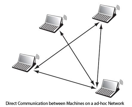
Figure illustrates the case of an ad-hoc network in which, to
get from one node to another, it may be necessary to traverse the intermediate
nodes. Many pitfalls can be on the road to building the routing table. For
example, signal for transmission, it is possible that the connection is not
symmetrical, a sense of communication are acceptable and not the other. The
routing table should reflect this. The radio signals are susceptible to
interference; asymmetric links can also be complicated by possible fainting
links.
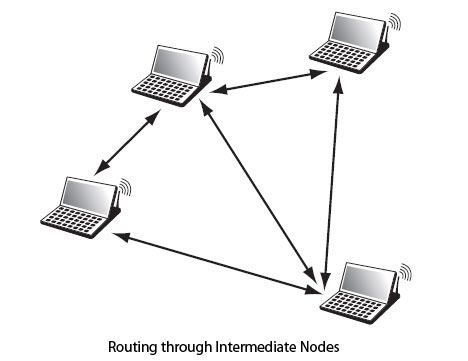
For all these reasons, the network routes to be constantly
modified, hence the eternal question discussed at the IETF: should maintain the
routing tables in the nodes of a mobile ad-hoc network? In other words, is it
worthwhile to keep updated routing tables ever changing, or is it not more
sensible to determine the routing table denier now?
As explained above, the reactive protocols work
by flooding to determine the best route when a packet stream is ready to be
issued. So there is no exchange of outside supervision control packets to
determine the path of the flood. The supervisory packet which is broadcast to
all neighboring nodes is played again by the neighboring nodes to reach the
receiver. Depending on the chosen technique, one can avail of the road
determined by the first supervision package that arrives at the receiver or
provide several routes in case of problems on the main road.
Proactive protocols behave totally differently. Supervision
packets are transmitted continuously in order to keep updated the routing table
by adding new lines and removing some. The routing tables are dynamic and
change according supervision packets arriving at the various nodes. A
difficulty in this case is to calculate a routing table that is compatible with
the routing tables of the different nodes so that there is no loop.
Another possibility is to find a compromise between the two
systems. That is to regularly calculate routing tables as the network is
lightly loaded. Thus, the performances of user streams in transit are not too
changed. When traffic increases, the updates are slowed. This method simplifies
the implementation of a reactive routing table when a request reaches the
network.
The proposed protocols for the normalization of the group are
summarized in MANET Table. Different metrics can be used to calculate the best
Road:
• The distance vectors give a weight to each link and add the
weights to determine the best route, which corresponds to the least
significant.
• The source routing to determine the best route as one that
allows the supervision package to arrive first to the recipient.
• The states of links indicate the links that are interesting
to take and those who are less so.
|
Metric
|
Reactive
|
Proactive
|
|
Vector distance
|
AODV (Ad-hoc On demand Distance Vector)
|
DSDV (Destination Sequence Distance Vector)
|
|
Source routing
|
DSR (Dynamic Source Routing)
|
|
|
Link Status
|
|
OLSR (Optimized LinkState Routing Protocol)
|
In conclusion, if MANET group studies are almost finished
regarding routing, almost everything remains to be done to the quality of
service, safety and power consumption.
The following briefly describes the two main routing
protocols in ad hoc networks MANET standardized by the group.
OLSR (Optimized
LinkState Routing)
OLSR (Optimized
Link State Routing) is certainly the most used ad-hoc routing protocols. It
is proactive type.
To avoid carrying too much supervision packets, OLSR relies
on the concept of multipoint relays, or MPR (MultipointRelay). The CPMs are
important nodes that have the distinction of being the best crossing points to
reach all the nodes in a flooding process without spreading in all directions.
The link state being sent by the MPR, it reduces all supervisory posts.
Knowledge of its neighbors is obtained by Hello messages that
are sent in broadcast. This helps to identify the neighbors and to send
the information status
necessary link to the routing algorithm. The Hello messages also indicate the
MPR to its neighbors. These Hello messages are intended only neighboring nodes
and can not be routed to a destination with two jumps. The structure of the
Hello packet is illustrated in Figure.
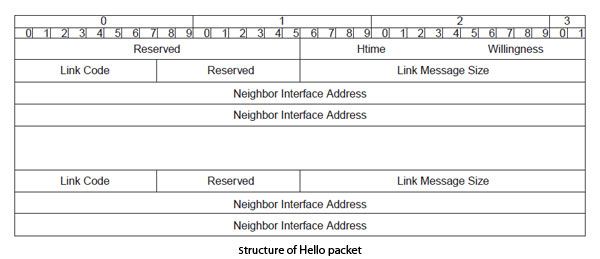
The Reserved field contains only 0, the HTime field indicates
the time interval between Hello, Willingness the application field to a node to
become a MPR, the Link Code field to pass the link state information between
transmitter and receivers indicated in the list of "Neighbor Interface
Address".
TC packets (Topology Control) are issued only by the MPR,
always with a broadcast address. The transmitted information indicates a list
of all the neighbors that have chosen this node as MPR and allows, through the
knowledge of all MPR and link state, to deduce the routing table. These
messages are broadcast across the network with a value of 255 in the TTL field.
The structure of the TC packet is shown in Figure.
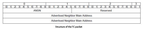
Wireless
Sensor Network Architecture and Its Applications
Currently, WSN (Wireless Sensor Network) is
the most standard services employed in commercial and industrial applications,
because of its technical development in a processor, communication, and
low-power usage of embedded computing devices. The WSN is built with nodes that
are used to observe the surroundings like temperature, humidity, pressure,
position, vibration, sound etc. These nodes can be used in various real-time
applications to perform various tasks like smart detecting, a discovery of
neighbor node, data processing and storage, data collection, target tracking,
monitor and controlling, synchronization, node localization, and effective
routing between the base station and nodes.
Presently, WSNs are beginning
to be organized in an enhanced step. It is not awkward to expect that in 10 to
15 years that the world will be protected with WSNs with entree to them via the
Internet. This can be measured as the Internet becoming a physical n/w. This
technology is thrilling with infinite potential for many application areas like
medical, environmental, transportation, military, entertainment, homeland
defense, crisis management and also smart spaces.
What is
a Wireless Sensor Network?
A Wireless Sensor Network is one kind of wireless network includes
a large number of circulating, self-directed, minute, low powered devices named
sensor nodes called motes. These networks certainly cover a huge number of
spatially distributed, little, battery-operated, embedded devices that are
networked to caringly collect, process, and transfer data to the operators, and
it has controlled the capabilities of computing & processing. Nodes are the
tiny computers, which work jointly to form the networks.
 Wireless Sensor Network
The
sensor node is a multi-functional, energy efficient wireless device. The
applications of motes in industrial are widespread. A collection of sensor
nodes collects the data from the surroundings to achieve specific application
objectives. The communication between motes can be done with each other using
transceivers. In a wireless sensor network, the number of motes can be in the
order of hundreds/ even thousands. In contrast with sensor n/ws, Ad Hoc
networks will have fewer nodes without any structure.
Wireless
Sensor Network Architecture
The most common WSN architecture follows the OSI architecture
Model. The architecture of the WSN includes five layers and three cross layers.
Mostly in sensor n/w we require five layers, namely application, transport,
n/w, data link & physical layer. The three cross planes are namely power
management, mobility management, and task management. These layers of the WSN
are used to accomplish the n/w and make the sensors work together in order to
raise the complete efficiency of the network.Please follow the below link
for: Types of wireless sensor
networks and WSN topologies
 Wireless Sensor Network Architecture
Application
Layer
The
application layer is liable for traffic management and offers software for
numerous applications that convert the data in a clear form to find positive
information. Sensor networks arranged in numerous applications in different
fields such as agricultural, military, environment, medical, etc.
Transport
Layer
The
function of the transport layer is to deliver congestion avoidance and
reliability where a lot of protocols intended to offer this function are either
practical on the upstream. These protocols use dissimilar mechanisms for loss
recognition and loss recovery. The transport layer is exactly needed when a
system is planned to contact other networks.
Providing
a reliable loss recovery is more energy efficient and that is one of the main
reasons why TCP is not fit for WSN. In general, Transport layers can be separated
into Packet driven, Event driven. There are some popular protocols in the
transport layer namely STCP (Sensor Transmission Control Protocol), PORT
(Price-Oriented Reliable Transport Protocol and PSFQ (pump slow fetch quick).
Network
Layer
The
main function of the network layer is routing, it has a lot of tasks based on
the application, but actually, the main tasks are in the power conserving,
partial memory, buffers, and sensor don’t have a universal ID and have to be
self-organized.
The
simple idea of the routing protocol is to explain a reliable lane and redundant
lanes, according to a convinced scale called metric, which varies from protocol
to protocol. There are a lot of existing protocols for this network layer, they
can be separate into; flat routing and hierarchal routing or can be separated
into time driven, query-driven & event driven.
Data
Link Layer
The
data link layer is liable for multiplexing data frame detection, data streams,
MAC, & error control, confirm the reliability of point–point (or)
point– multipoint.
Physical
Layer
The
physical layer provides an edge for transferring a stream of bits above
physical medium. This layer is responsible for the selection of frequency,
generation of a carrier frequency, signal detection, Modulation & data
encryption. IEEE 802.15.4 is suggested as typical for low rate particular areas
& wireless sensor network with low cost, power consumption, density,
the range of communication to improve the battery life. CSMA/CA is used to
support star & peer to peer topology. There are several versions of IEEE
802.15.4.V.
Characteristics
of Wireless Sensor Network
The
characteristics of WSN include the following.
·
The
consumption of Power limits for nodes with batteries
·
Capacity to
handle with node failures
·
Some mobility
of nodes and Heterogeneity of nodes
·
Scalability
to large scale of distribution
·
Capability to
ensure strict environmental conditions
·
Simple to use
·
Cross-layer
design
Advantages of Wireless Sensor Networks
The advantages of WSN include the following
·
Network
arrangements can be carried out without immovable infrastructure.
·
Apt for the
non-reachable places like mountains, over the sea, rural areas and deep
forests.
·
Flexible if
there is a casual situation when an additional workstation is required.
·
Execution
pricing is inexpensive.
·
It avoids
plenty of wiring.
·
It might
provide accommodations for the new devices at any time.
·
It can be
opened by using a centralized monitoring.
Wireless
Sensor Network Applications
Wireless
sensor networks may comprise of numerous different types of sensors like low
sampling rate, seismic, magnetic, thermal, visual, infrared, radar, and
acoustic, which are clever to monitor a wide range of ambient situations.
Sensor nodes are used for constant sensing, event ID, event detection &
local control of actuators. The applications of wireless sensor network mainly
include health, military, environmental, home, & other commercial
areas.
·
Military
Applications
·
Health
Applications
·
Environmental
Applications
·
Home
Applications
·
Commercial
Applications
·
Area
monitoring
·
Environmental/Earth
sensings
·
Air pollution
monitoring
·
Forest fire
detection
·
Landslide
detection
·
Water quality
monitoring
Wireless Communication - TCP/IP
Layers in the TCP/IP
Suite
The four layers of the
TCP/IP model are the host-to-network layer, internet/network layer, transport
layer and the application layer. The purpose of each layer in the TCP/IP
protocol suite is detailed below.

The above image
represents the layers of TCP/IP protocol suite.
Physical Layer
TCP/IP does not define
any specific protocol for the physical layer. It supports all of the standard
and proprietary protocols.
·
At this level, the communication is between two hops or nodes,
either a computer or router. The unit of communication is a single bit.
·
When the connection is established between the two nodes, a stream
of bits is flowing between them. The physical layer, however, treats each bit
individually.
The responsibility of
the physical layer, in addition to delivery of bits, matches with what
mentioned for the physical layer of the OSI model, but it mostly depends on the
underlying technologies that provide links.
Data Link Layer
TCP/IP does not define
any specific protocol for the data link layer either. It supports all of the
standard and proprietary protocols.
·
At this level also, the communication is between two hops or
nodes. The unit of communication however, is a packet called a frame.
·
A frame is a packet that encapsulates the data
received from the network layer with an added header and sometimes a trailer.
·
The head, among other communication information, includes the
source and destination of frame.
·
The destination address is needed to define the
right recipient of the frame because many nodes may have been connected to the
link.
·
The source address is needed for possible
response or acknowledgment as may be required by some protocols.
LAN, Packet Radio and
Point-to-Point protocols are supported in this layer
Network Layer
At the network layer,
TCP/IP supports the Internet Protocol (IP). The Internet Protocol (IP) is the
transmission mechanism used by the TCP/IP protocols.
- IP transports
data in packets called datagrams, each of which is transported
separately.
- Datagrams can
travel along different routes and can arrive out of sequence or be
duplicated.
IP does not keep track
of the routes and has no facility for reordering datagrams once they arrive at
their destination.
Transport Layer
There is a main
difference between the transport layer and the network layer. Although all
nodes in a network need to have the network layer, only the two end computers
need to have the transport layer.
·
The network layer is responsible for sending individual datagrams
from computer A to computer B; the transport layer is responsible for
delivering the whole message, which is called a segment, from A to
B.
·
A segment may consist of a few or tens of datagrams.
The segments need to be broken into datagrams and each datagram has to be
delivered to the network layer for transmission.
·
Since the Internet defines a different route for each datagram,
the datagrams may arrive out of order and may be lost.
·
The transport layer at computer B needs to wait until all of these
datagrams to arrive, assemble them and make a segment out of them.
Traditionally, the
transport layer was represented in the TCP/IP suite by two protocols: User
Datagram Protocol (UDP) and Transmission Control Protocol
(TCP).
A new protocol
called Stream Control Transmission Protocol (SCTP) has been
introduced in the last few years.
Application Layer
The application layer in
TCP/IP is equivalent to the combined session, presentation, and application
layers in the OSI model.
·
The application layer allows a user to access the services of our
private internet or the global Internet.
·
Many protocols are defined at this layer to provide services such
as electronic mail file transfer, accessing the World Wide Web, and so on.
·
The protocols supported in this layer are TELNET, FTP and HTTP.
Network Applications
Computer systems and
peripherals are connected to form a network.They provide numerous advantages:
- Resource
sharing such as printers and storage devices
- Exchange of
information by means of e-Mails and FTP
- Information
sharing by using Web or Internet
- Interaction
with other users using dynamic web pages
- IP phones
- Video
conferences
- Parallel
computing
- Instant
messaging
Effect of User Mobility on Communication
Systems
- At the physical layer, channel characteristics vary
with the location of the user and because of mobility, vary in time.
Because antennas mounted on vehicles have rather unfavourable positions
and little 'clearance', the propagation characteristics in the mobile radio channel are
notoriously poor. A mobile radio link is hindered by a number of
propagation mechanisms, viz., multipath scattering from objects near the mobile antenna, shadowing by dominant obstacles and attenuation mechanisms
on the propagation path between transmitter and receiver.
Multipath
reception causes rapid fluctuations of the received signal power, whereas
shadowing is experienced as a slow amplitude effect. Adaptive transmit power
control can mitigate the adverse effects of individual shadowing to some
extent. Since most mobile networks are interference-limited rather than
noise-limited, interfering signals are likely to produce substantially greater
adverse collective impact if adaptive power control is used to overcome
shadowing on their own transmission path. Mobile systems must live with signal
fluctuations during transmission. Because of high demands on spectrum
efficiency, extensive frequency re-use and mutual interference must be accepted.
This means that the classical system analysis inspired by the stationary AWGN channel of conventional information theory
may not be applicable.
- At the data link layer, channel coding is to be chosen
in accordance with the specific character of the fading radio channel. In
contrast to AWGN channels with errors randomly distributed in time, bursts
(i.e., clusters of) errors are experienced in the mobile channel. A
typical mobile channel allows relatively reliable communication during
certain periods, interrupted by other periods of particularly poor communication.
The latter are called 'fades'.
- At the network layer, the routing of signals may change from time to time as the user moves through the
service area of the network. This may require localisation of the terminal
(or localisation of a specific user in more sophisticated 'personal'
communication systems) to find optimum routing.
- Transport layer protocols and applications should anticipate to fading and channel throughput fluctuations.
This many be at odds with strictly OSI layered protocol stacks.
- At the presentation layer, improved (speech and video) source coding techniques have helped in achieving
acceptable spectrum efficiency with digital systems.
- At the application layer (and above), personal mobility
and transportation of goods require specific services and
facilities.
file system
A file system typically
manages operations, such as storage management, file naming,
directories/folders, metadata, access rules and privileges. Commonly used file
systems include File Allocation Table 32 (FAT 32),
New Technology File System (NTFS) and Hierarchical File
System (HFS).
Database is a collection of
related data and data is a collection of facts and figures that can be
processed to produce information.
Mostly data represents
recordable facts. Data aids in producing information, which is based on facts.
For example, if we have data about marks obtained by all students, we can then
conclude about toppers and average marks.
A database
management system stores data in such a way that it becomes easier to
retrieve, manipulate, and produce information.
 WWW stands for World Wide Web. A technical
definition of the World Wide Web is : all the resources and users on the
Internet that are using the Hypertext Transfer Protocol (HTTP).
WWW stands for World Wide Web. A technical
definition of the World Wide Web is : all the resources and users on the
Internet that are using the Hypertext Transfer Protocol (HTTP).
A broader definition comes from the organization that Web
inventor Tim Berners-Lee helped found, the World Wide
Web Consortium (W3C).
The World Wide Web is the universe of network-accessible
information, an embodiment of human knowledge.
In simple terms, The World Wide Web is a way of exchanging
information between computers on the Internet, tying them together into a vast
collection of interactive multimedia resources.
Internet and Web is not the same thing: Web uses
internet to pass over the information.
WAP - Introduction

WAP - Introduction
[WAP is] the de facto
worldwide standard for providing Internet communications and advanced telephony
services on digital mobile phones, pagers, personal digital assistants, and
other wireless terminals − WAP Forum.
WAP stands for Wireless Application Protocol.
The dictionary definition of these terms are as follows −
·
Wireless − Lacking or not
requiring a wire or wires pertaining to radio transmission.
·
Application −
A computer program or piece of computer software that is designed to do a specific
task.
·
Protocol − A set of
technical rules about how information should be transmitted and received using
computers.
WAP is the set of rules
governing the transmission and reception of data by computer applications on or
via wireless devices like mobile phones. WAP allows wireless devices to view
specifically designed pages from the Internet using only plain text and very
simple black-and-white pictures.
WAP is a standardized
technology for cross-platform, distributed computing very similar to the Internet's
combination of Hypertext Markup Language (HTML) and Hypertext Transfer Protocol
(HTTP), except that it is optimized for:
·
low-display capability
·
low-memory
·
low-bandwidth devices, such as personal digital assistants (PDAs),
wireless phones, and pagers.
DCN - Application Layer Introduction
Application layer is the top most layer in OSI and TCP/IP layered
model. This layer exists in both layered Models because of its significance, of
interacting with user and user applications. This layer is for applications
which are involved in communication system.
A user may or may not directly interacts with the applications.
Application layer is where the actual communication is initiated and reflects.
Because this layer is on the top of the layer stack, it does not serve any
other layers. Application layer takes the help of Transport and all layers
below it to communicate or transfer its data to the remote host.
When an application layer protocol wants to communicate with its
peer application layer protocol on remote host, it hands over the data or
information to the Transport layer. The transport layer does the rest with the
help of all the layers below it.

There’is an ambiguity in understanding Application Layer and its
protocol. Not every user application can be put into Application Layer. except
those applications which interact with the communication system. For example,
designing software or text-editor cannot be considered as application layer
programs.
On the other hand, when we use a Web Browser, which is actually
using Hyper Text Transfer Protocol (HTTP) to interact with the network. HTTP is
Application Layer protocol.
Another example is File Transfer Protocol, which helps a user to
transfer text based or binary files across the network. A user can use this
protocol in either GUI based software like FileZilla or CuteFTP and the same user
can use FTP in Command Line mode.
Hence, irrespective of which software you use, it is the protocol
which is considered at Application Layer used by that software. DNS is a
protocol which helps user application protocols such as HTTP to accomplish its
work.


No comments:
Post a Comment